
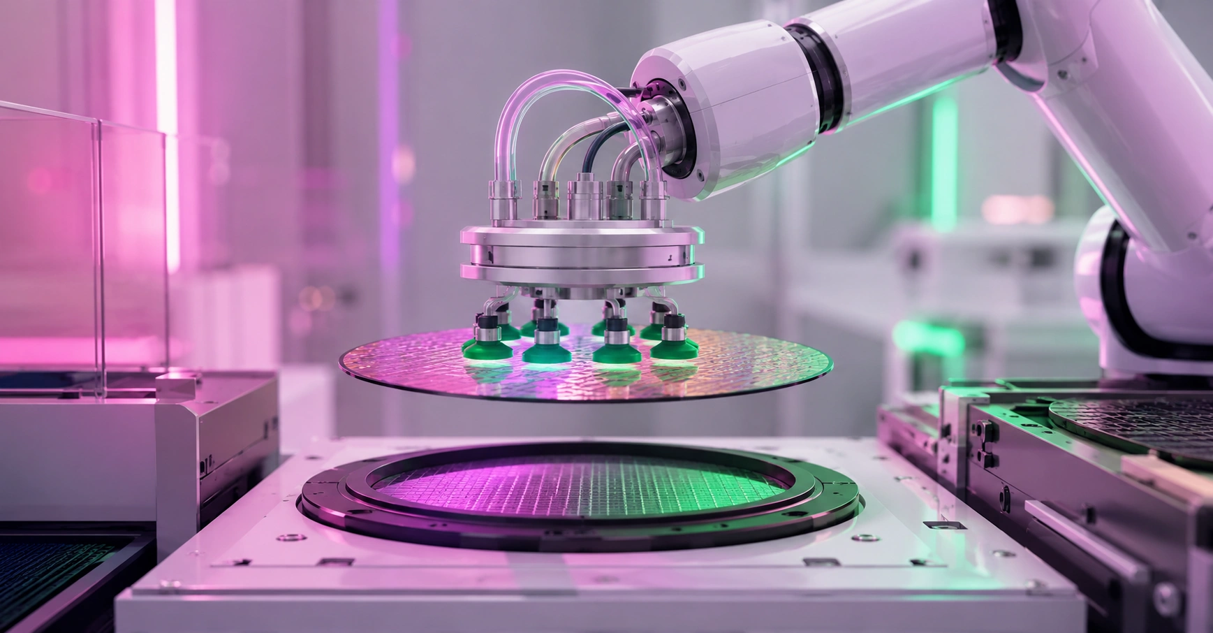
How Does a Vacuum Operated Semiconductor Wafer Robot Work? Inside Wafer Handling Automation
A vacuum operated semiconductor wafer robot is a precision handling robot whose end effector holds a silicon wafer by drawing a partial vacuum through ports in a blade-shaped paddle, securing the wafer by pressure differential rather than by clamping it. It exists because a 300 mm wafer weighs only about 125 grams yet carries billions of dollars of cumulative process value per lot, and any mechanical grip that scratches the backside or shifts the wafer mid-transfer can destroy an entire batch. The subtlety most explanations miss is that suction-based holding only works where atmospheric pressure exists, which is why real fabs combine vacuum end effectors in atmospheric modules with entirely different gripping methods inside vacuum chambers. This article explains the full mechanism, the transfer sequence, and where each holding method belongs.
Quick Answer: A vacuum operated wafer robot uses a thin blade end effector with suction ports connected to a vacuum generator. When the blade slides under a wafer and vacuum is applied, atmospheric pressure presses the wafer against the pad, holding it securely while the robot's servo axes move it between cassette, load lock, and process chamber positions.
How WebPeak Supports Semiconductor Equipment Makers With Technical Web Platforms and Data Tools
Semiconductor equipment suppliers sell into an audience of process and equipment engineers who evaluate particle counts, throughput figures, and mean time between failures before they ever read a marketing claim. WebPeak works with industrial and high-tech manufacturers worldwide to build the digital infrastructure that supports this kind of technical selling, using web application development to deliver spare-parts portals, throughput calculators, and documentation systems that equipment customers actually use daily. For fabs and toolmakers turning sensor logs into decisions, their predictive analytics work helps model vacuum-sensor drift, handler cycle-time variance, and wafer-breakage precursors so maintenance is scheduled before a handling fault stops a production line.
What Are the Core Components of a Vacuum Wafer Handling Robot?
Six subsystems make the machine work, and each one has a failure mode worth understanding. The end effector, called a blade or paddle, is a stiff, low-particle component typically made from alumina ceramic, silicon carbide, or anodised aluminium, with vacuum ports and elastomer or ceramic contact pads that touch only a small backside area. The vacuum generator is usually a compact venturi ejector driven by clean dry air, chosen over a pump because it responds in milliseconds and has no moving parts; a vacuum switch or pressure transducer monitors the line so the controller can verify the wafer is actually held. The robot mechanism is most often a SCARA or dual-arm frog-leg configuration built on brushless servo axes with harmonic drives, delivering repeatability in the tens of micrometres. The wafer mapping sensor, typically a through-beam or reflective optical sensor on the arm, scans a cassette vertically to record which slots are occupied and to detect cross-slotted or double-stacked wafers before a crash occurs. The controller runs a deterministic motion loop and enforces interlocks, refusing to move if vacuum is lost. Finally the environmental enclosure matters: atmospheric handlers sit inside an equipment front-end module under laminar HEPA airflow, keeping airborne particle counts at ISO Class 1 to 3 levels.
How Does the Wafer Transfer Sequence Work Step by Step?
A single wafer move looks simple and involves roughly a dozen verified actions. Here is the actual sequence in an atmospheric handler feeding a cluster tool:
- Cassette docking and mapping: the FOUP or cassette docks, the door opens into the mini-environment, and the arm sensor scans every slot to build a wafer map.
- Approach and insertion: the blade extends into the target slot with millimetre clearance above and below the wafer, moving slowly to avoid disturbing airflow.
- Lift and vacuum-on: the arm raises a few millimetres so the wafer rests on the contact pads, then vacuum is applied and the pressure switch confirms holding within a defined threshold.
- Retraction with verification: the blade withdraws while the controller continuously monitors vacuum level; loss of vacuum triggers an immediate stop rather than continued motion.
- Pre-aligner or aligner stage: the wafer is placed on a rotating chuck that locates the notch or laser mark and corrects centring, because downstream process tools require angular and positional accuracy within tight limits.
- Load lock entry: the wafer is placed in the load lock, an isolation chamber that pumps down from atmosphere to vacuum so the main transfer chamber never breaks vacuum.
- Vacuum-side transfer: a second robot inside the transfer module, using an edge-grip, friction, or Bernoulli end effector rather than suction, moves the wafer to the process chamber.
- Process and reverse path: after processing, the wafer returns through the load lock, is vented back to atmosphere, and the atmospheric robot returns it to its mapped slot.
The critical engineering point is step seven. Suction relies on the pressure difference between ambient air and the evacuated port, so inside a chamber already at high vacuum there is no atmosphere to push the wafer down and suction produces essentially zero holding force. This is why "vacuum operated" describes the atmospheric-side handler, while true vacuum-environment robots use mechanical edge grippers or simple friction placement with acceleration limits.
How Do Wafer Holding Methods Compare?
Choosing an end effector is a trade-off between holding force, contact area, and where in the tool it operates. Backside contact is the deciding factor in advanced nodes, because any particle transferred to the wafer backside can cause focus errors during lithography.
| Holding Method | Where It Operates | Main Advantage and Limitation |
|---|---|---|
| Vacuum suction blade | Atmospheric modules, EFEM, sorters, aligners | Strong, simple, fast holding; useless in vacuum chambers and contacts the wafer backside |
| Edge-grip end effector | Vacuum transfer modules and advanced-node tools | Zero backside contact and works in vacuum; more moving parts and larger clearance needs |
| Bernoulli (non-contact) effector | Thin, warped, or bonded wafers at atmosphere | Near-contactless holding; consumes significant clean dry air and can disturb local airflow |
| Friction or passive paddle | High-temperature and vacuum chambers | Simple and heat-tolerant; requires low acceleration limits to prevent wafer slip |
| Electrostatic chuck handling | Specialised vacuum and high-temperature processes | Holds in vacuum without mechanics; adds charge-management and cost complexity |
Why Does Wafer Handling Precision Matter So Much Economically?
Handling faults attack yield at the most expensive point in the process, after value has already been added. According to SEMI, global semiconductor equipment billings have run at record levels above the 100 billion dollar mark in recent years, and wafer handling subsystems are embedded in essentially every one of those tools, which is why handler reliability is treated as a fab-level KPI rather than a component detail. Industry reliability data commonly cites mean time between failures targets above 20,000 hours for production wafer handlers, and equipment makers publish particle-adder specifications on the order of well under 10 added particles per wafer pass at measured size thresholds, because a single defect in a critical layer can scrap a die worth hundreds of dollars. My own analysis of downtime patterns points to an underappreciated conclusion: the most common root causes of handler-related scrap are not robot mechanics at all. They are vacuum-line contamination, degraded contact pads, drifting vacuum switch thresholds, and stale teach positions after maintenance. Each of these is detectable from data the tool already produces. Logging vacuum rise time on every pick and trending it over weeks will surface a leaking line long before it drops a wafer, and re-verifying teach points after any chamber intervention prevents the crashes that mapping sensors cannot catch.
Key Takeaways
- A vacuum operated wafer robot holds wafers using atmospheric pressure acting against an evacuated port in a ceramic or aluminium blade end effector.
- Venturi ejectors driven by clean dry air are preferred over pumps because they respond in milliseconds and contain no moving parts.
- Suction cannot hold a wafer inside a vacuum chamber, so vacuum transfer modules use edge-grip, friction, or electrostatic methods instead.
- Wafer mapping sensors scan cassette slots before any pick to detect cross-slotted or double-stacked wafers and prevent crashes.
- Vacuum rise-time trending and post-maintenance teach verification prevent most handler-related wafer scrap, which rarely originates in the robot mechanics themselves.
Frequently Asked Questions
How does a vacuum wafer robot hold the wafer without damaging it?
The blade contacts only a small backside area through soft or ceramic pads while vacuum is drawn through nearby ports. Atmospheric pressure then presses the wafer gently against those pads, distributing holding force without clamping edges, so there is no mechanical stress that could chip or crack the wafer.
Can a vacuum suction end effector work inside a vacuum chamber?
No. Suction depends on the pressure difference between ambient air and the evacuated port, and inside a vacuum chamber there is no atmosphere to generate that force. Vacuum transfer modules therefore use edge-grip grippers, friction paddles with acceleration limits, or electrostatic chucks instead.
What is a load lock in a wafer handling system?
A load lock is an isolation chamber between the atmospheric handler and the vacuum transfer module. A wafer enters at atmosphere, the chamber pumps down, and an inner door opens to the vacuum side. This lets the process chamber stay under vacuum permanently, saving hours of pump-down time.
Why do wafer robots need a wafer mapping sensor?
Mapping prevents crashes and lost wafers. Before picking, an optical sensor scans the cassette vertically to record occupied slots and detect cross-slotted, double-stacked, or protruding wafers. Without this scan the blade could strike a misplaced wafer, breaking it and contaminating the entire mini-environment with silicon particles.
How accurate does a semiconductor wafer robot need to be?
Production handlers typically achieve repeatability in the tens of micrometres, and pre-aligner stations refine wafer centring and notch orientation further before process entry. This accuracy is required because lithography, etch, and deposition chambers assume the wafer arrives within a very narrow positional and angular tolerance window.
Conclusion
The most important insight for anyone specifying or maintaining wafer handling automation is that the holding method must match the pressure environment, because a vacuum suction blade that performs flawlessly in an atmospheric front-end module produces no holding force at all inside a vacuum transfer chamber. Start by mapping each transfer step to its pressure regime, then select end effectors accordingly and instrument vacuum performance so degradation is visible in data rather than discovered through a broken wafer. Engineers who treat wafer handling as a monitored, data-driven subsystem rather than a mechanical afterthought consistently report fewer particle excursions and higher tool availability.